Calculated Fields
Calculated Fields are used for two purposes:
to calculate new sensor readings from other readings that are in the sensor database.
to add sensor readings gathered from the Internet. The current implementation allows for acquisition of temperature and wind speed data from Internet weather services.
A Calculated Field uses the same editing form in BMON as a standard Sensor does. So, to add a Calculated Field, you follow the normal procedure for adding a Sensor, as described in Add Buildings and Sensors. The important configuration differences relative to a standard sensor are:
For a Calculated Field, you need to create your own Sensor ID for the calculated field. The Sensor ID must be unique across the entire BMON set of Sensors. The Sensor ID needs to be 30 characters or less, using numbers and letters but no spaces.
In the Sensor editing form, you need to make sure that the
Calculated Fieldbox is checked.
The BMON system processes Calculated Fields every one-half hour. If the calculated fields involve sensors that report more frequently than every half hour, multiple calculated sensor readings will be generated at each half-hour processing interval to match up with the frequency of the source sensors.
Mathematical Calculated Fields
It is possible to create a calculated field by doing mathematical operations on one or more other sensor fields (a limit of five sensor fields can be involved in the calculation). For example, if you want to plot and analyze the difference in temperature between two sensors, you can create a new calculated “sensor” that is the difference in value between two other sensors. Below is a screen shot of how you would configure that calculated field.
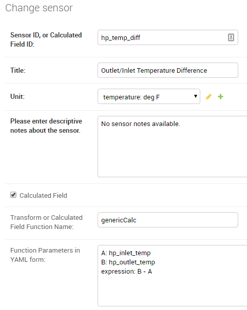
This new calculated field has the Sensor ID of hp_temp_diff, and the
values in that field are calculated as the difference between sensors
with the IDs of hp_outlet_temp and hp_inlet_temp.
Not only are these calculated fields useful for plotting and analysis, they also extend the capabilities of the Alerting system, as described in Sensor Alerts. Complex alerts can be created by configuring a calculated field involving multiple sensors. Then, an Alert condition can be added to that calculated field. Thus, the Alert will depend on the state of multiple sensors, since multiple sensors feed the calculated field.
These calculated fields involving general mathematical expressions must have
genericCalc entered in the “Transform or Calculated Field Function Name” box.
This is the name of the function that allows for general calculations to be
done using one or more existing sensor fields.
Remaining configuration of the calculated field occurs in the “Function Parameters in YAML form” input box. Each one of the possible function parameters is described below.
A(required: a Sensor ID)The value of this parameter is the Sensor ID of the sensor that will be used as the
Avariable in the mathematical expression. At least one sensor needs to be involved in the calculation of the new field, so that is why theAparameter is required.B,C,D,E(optional: a Sensor ID for each parameter used)Four additional sensors can be involved in the calculation. Use any of the parameter names of B through E to give the Sensor IDs of those additional sensors involved in the calculated field.
expression(required: a math or boolean expression, described below)Use this parameter to write out the math expression for the calculated field. You can use any of the sensor variables A through E that were included as parameters, and the values from these sensors will be used in the calculation. The expression must be a valid Python expression, and any of the functions in the Python
mathlibrary can be included; see the math library documentation.Here are some valid expressions:
An example of an expression using function from the Python math library, using three sensors as inputs (A, B and E):
expression: 3.4 * A * sin(B) + sqrt(E)
An example of a Boolean expression. A
Truevalue from this expression is represented as a sensor value of 1.0 and aFalsevalue is represented as 0.0. An important note, when testing for equality with a Python expression, you must use a double equal sign (==) and not a single equal sign. The expression below will result in a calculated field value of 1.0 if Sensor A has a value equal to 1.0 and Sensor B has a value greater than 34.3; otherwise, the calculated value will be 0.0:expression: (A == 1.0) and (B > 34.3)
averaging_hours(optional: a number of hours, fractional hours allowed; default is no averaging)If you include this parameter, it will cause sensor values to be averaged over the requested time interval before being used in the expression. So, if
averaging_hoursis 0.5, any sensor values will be averaged over half-hour intervals before they are used in the calculation.rolling_average(optional: the valueTrueorFalse, default isFalse)When this parameter is
False, the default, each averaging interval for the sensor values is distinct and does not overlap with other intervals. For example, ifaveraging_hoursis set to 4.0, sensors will be averaged over 6 different periods across the day: Midnight to 4 am, 4 am - 8 am, etc. And, 6 calculated values will be produced corresponding to each one of those intervals. However, ifrolling_averageis set toTrue, a new calculated value will be computed for each and every timestamp that is present for sensor A. For example, if sensor A has a reading at 10:30 am, theaveraging_hoursis set to 2.0, androlling_averageisTrue, all sensors involved in the calculation will be averaged over the period of 8:30 am - 10:30 am (the 2 hours preceding sensor A’s timestamp), and a new calculated value will be created for that time interval. If another sensor A reading is present for 10:40 am, and new calculated value will be computed for the 8:40 am - 10:40 am period. So, there will be overlap in the time periods used for computing the new calculated field values, and many calculated readings will be generated even ifaveraging_hoursis set to a large value.time_label(optional: the valueleft,right, orcenter, default iscenter)If time averaging is being used in the calculations (i.e. the parameter
averaging_hourshas a value), then thistime_labelparameter determines where the timestamp for the new calculated reading will be placed. The default iscenter, which places the timestamp at the center of the time interval encompassing the averaged readings. For example, if the averaging period is Midnight to 4 am andcenterplacement is being used, the timestamp for the calculated reading will be at 2 am. Ifleftis specified, the timestamp is at the earliest edge of the interval, Midnight in this example. Ifrightis specified, the timestamp will be at the latest edge of the interval, 4 am in this example. This parameter is also relevant rolling averages are being computed.
Note
If time averaging is not being used in the calculation, here is the procedure for determining the values and timestamps used in the calculated field. First, timestamps for the calculated field are aligned with the timestamps for Sensor A; i.e there will be a reading generated for every timestamp present for Sensor A. Next, other sensor timestamps may not perfectly align with those from Sensor A; for those other sensors, their values are linearly interpolated to match up with Sensor A timestamps before being used in the calculation.
Acquiring Weather Data from the Internet
BMON can currently access outdoor dry-bulb temperature, wind speed, and relative humidity data from the National Weather Service and dry-bulb temperature and wind speed from the Weather Underground service. Here is an example of the needed configuration for the National Weather Service:
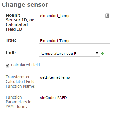
In the first box, a Sensor ID has been created, in this example:
elmendorf_temp. Title and Unit entries are filled out as
they are for standard sensors. The Calculated Field box must be
checked. For gathering outdoor dry-bulb temperature, the
Transform or Calculated Field Function Name must contain the value
getInternetTemp (correct capitalization is critical and must be as
shown). Finally, the Function Parameters in YAML form box must have
an entry of stnCode: plus a 4 character National Weather Service
station code, in this example (there must be
a space after the colon):
stnCode: PAED
The only changes necessary to acquire a wind speed value in miles per
hour is to enter getInternetWindSpeed into the
Transform or Calculated Field Function Name box, change the Unit
to velocity: mph, and enter an appropriate Sensor ID and Title.
Acquiring relative humidity data in % RH requires entering
getInternetRH into
theTransform or Calculated Field Function Name box, and making
appropriate unit and title changes elsewhere.
The MesonetAPI service includes a larger set of weather stations.
To gather temperature or wind data from this service, you must first acquire a
Mesonet API Token and enter
that key into the BMON Settings File
as the BMSAPP_MESONET_API_TOKEN setting (restarting the Django web
application after changing a setting is necessary).
There is currently no charge for limited use of the API up to 5,000 requests and 5 million service units per month. Beyond that there is charge of 5 cents per thousand requests, and 15 cents per million Service Units. If either your Requests or Service Units exceed the free tier levels, you will be charged a $5.00 monthly service fee, in addition to the rated charges for any usage above the free tier levels. See the Mesonet Pricing Page for more information.
Here is an example configuration for acquiring temperature data from the service:
Calculated Field |
|
|---|---|
Transform or
Calculated Field
Function Name:
|
getAllMesonetTemperature |
Function
Parameters in
YAML form:
|
stn: F2072request_interval_hours: 2since: 6/1/2019 |
The key differences from the National Weather Service configuration are:
getAllMesonetTemperaturemust be entered into theTransform or Calculated Field Function Namebox. If you are acquiring wind speed data, then the correct entry isgetAllMesonetWindSpeed. Capitalization must be as shown.The
Function Parametersbox must contain astnentry for the weather station you want data from. To find station codes, refer to the Mesonet map.The
Function Parametersbox may contain an additional entry for therequest_interval_hourswhich specifies the minimum interval at which data is updated. To stay within the limit of 5,000 requests per month, the interval can be 0.5 for up to three calculated sensors or 2.0 for up to 13. To estimate the minimum interval you can take the total number of fields that will use the mesonet API and multiply by 0.15. The default is two hours.The
Function Parametersbox may also contain an additionalsinceentry which specifies the earliest date or date/time to retieve data for.
Converting On/Off Events into Runtime Fraction
Some sensors record the precise time of On and Off events. An example of such a sensor is a Monnit Dry Contact sensor. This sensor posts a reading every time its two contacts are closed or are opened, and the sensor is often used to record when a device turns on and turns off. In addition to seeing the exact times a device turned on and turned off, it is often useful to record the percentage of time that the device was on during evenly spaced intervals.
To provide this additional information, a special Calculated Field
function is provided in BMON. The function will create a separate
“sensor” in the BMON system that shows the fraction of time that a
device was On for every half-hour interval (or other user-configurable
interval). This function is called runtimeFromOnOff, and here is an
example of its use:
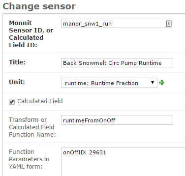
The Unit entry generally should be runtime: Runtime Fraction or
fraction: Occupied Fraction. runtimeFromOnOff must be entered as
the Transform or Calculated Field Function Name. Finally, you need
to provide the Sensor ID of the sensor that records the precise On and
Off times (that sensor needs to report a value of 1 when the device
turns on and a value of 0 when the device turns off). That Sensor ID is
entered as the onOffID parameter in the Function Parameters box:
onOffID: 29631
In this example, the Sensor ID is 29631, an ID of a Monnit Dry
Contact sensor. By default, this function will calculate the runtime
fraction for every half-hour interval. If you would like to use a
different interval, add a second line to the Function Parameters
box. For the above example, the following would be the entry for
calculating 15 minute runtime fractions:
onOffID: 29631
runtimeInterval: 15
This special runtime function is also useful with Motion or Occupancy Sensors and 1-Wire Motor Sensors used with the Mini-Monitor.
Calculating Rate of Use from a Liquid Tank such as Fuel Tank
Sensors are available that can determine the depth of liquid in a tank. One example of such a sensor is an ultrasonic distance measuring sensor mounted on the top of the tank looking down at the liquid in the tank. Pressure sensors can be used to determine the depth of liquid in a tank. While the depth of liquid in the tank is a useful quantity to measure and display, it is also useful to know how fast the liquid is leaving the tank; i.e. the rate-of-use of the liquid.
The tankUse calculated sensor function is available to create a new calculated
sensor that shows the rate-of-use from a tank. The function needs two sensors to
supply the data for determining rate of use:
A sensor that reports depth of liquid in the tank in inches. For a distance-meansuring sensor mounted at the top of the tank looking downward, a sensor Transform can be entered, e.g.
39.41 - val, that converts the distance measured to the liquid surface into a liquid depth. Determining the constant in this Transform can be done by recording a liquid depth reading from a sight glass or a dipstick at a time when a sensor reading of the distance to liquid surface is available. The 39.41 value in the prior formula was determined by adding a dipstick reading of 22.25 inches to a distance-to-liquid reading of 17.16 inches.A sensor that measures the temperature near the tank, or on the tank wall. Liquids expand and contract with temperature, and some sensors themselves change their readings with temperature, so the
tankUsefunction uses the temperature readings to factor out temperature impacts on the liquid depth measurement.
The screenshot below shows a basic use of the tankUse function:
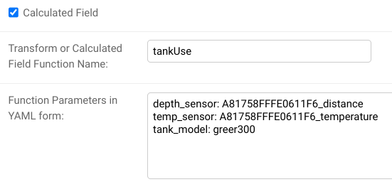
The depth_sensor and temp_sensor parameters are required and give the Sensor IDs of
the two sensors previously described. The depth sensor must report inches of liquid depth.
The temperature sensor can report in any units and be located on or near the tank (on the tank
is most accurate.) The tank_model parameter identifies the model of tank being measured.
Only certain Greer tanks are known by the function, but other tanks can be modeled through
use of tank geometry parameters described below. As set up above, this function will report
daily-average BTU/hour of usage from the tank, assuming the tank contains #1 Heating Oil.
Note that the most recent data points created by the function will be updated in subsequent runs of the function to improve accuracy. Estimating rate-of-use from a tank has better accuracy when data before and after the reporting period is available.
Here is the full list of available parameters for the function:
depth_sensor Parameter, required
The Sensor ID of the liquid depth sensor, which must report in inches.
temp_sensor Parameter, required
The Sensor ID of the temperature sensor, mounted on or in the tank (most accurate), or near the tank. The sensor can report in any units.
tank_model Parameter, optional
The function needs to know the size and shape of the tank. Certain models of tanks are
known by the function, and if your tank is one of those, this parameter can be
used to identify the tank model. A number of Above Ground Single Wall UL 142 tanks from
Greer are known by the function. The tank_model ID and tank model of known tanks
are shown below:
greer300: 300 gallon Greer tank (horizontal, cylindrical)greer500: 500 gallon Greer tank (horizontal, cylindrical)greer1000: 1,000 gallon Green tank (horizontal, cylindrical)greer1500: 1,500 gallon Green tank (horizontal, cylindrical)
If you do not specify a tank_model, you must specify both a tank_gallons and
a tank_max_depth parameter, described below.
tank_gallons Parameter, optional
If tank_model is not specified, you must provide the tank_gallons parameter, giving
the tank capacity measured in gallons.
tank_max_depth Parameter, optional
If tank_model is not specified, you must provide the tank_max_depth parameter.
The tank_max_depth parameter gives the liquid depth that occurs when the tank is full.
The parameter must be expressed in inches.
linear Parameter, optional, default value: False
If linear is set to False, the default, the tank is assumed to be a horizontal, cylindrical
tank. If linear is True, then the volume of liquid in the tank is assumed to be directly
proportional to depth of liquid; this is true for vertical, cylindrical and rectangular tanks.
In general, it is true for any tank where the horizontal cross-sectional area does not change across the
usable height of the tank. Note that if the tank_model parameter is entered, then the linear
parameter is forcibly set to a value consistent with the chosen tank_model; a user-entered value is
ignored.
report_hours Parameter, optional, default value: 24
The function reports tank usage for fixed intervals of time. This parameter controls how
long those intervals are. The default value of 24 (expressed in hours) means that usage
will be reported for daily intervals. Given current sensor technology, it is
recommended that report_hours values be set to 24 or greater. Sub-day resolution is
not accurate given the temperature and noise effects experienced by tank depth sensors.
measure Parameter, optional, default value: btu
The function can report rate-of-use from the tank in two different units of measure: BTU/hour
and gallons/hour. To select BTU/hour, measure should be set to btu, which is the
default. To select gallons/hour, measure should be set to gallon.
fuel_btus Parameter, optional, default value: 137452
If the measure selected is btu, this parameter gives the number of BTUs in a gallon
of tank fuel, defaulting to 137,452 BTUs/gallon, which is appropriate for #1 Heating Oil.
Storing the Raw Count Values from a Rate-of-Change Sensor
Note: this function is not needed with the current BMON release, as every counter-type sensor that uses a “rate” transform will automatically generate a second sensor that holds the cumulative count. This sensor will have the Sensor ID of the original sensor plus the suffix “_raw”.
Counter type sensors generally use a Transform function to transform the cumulative count registered by the sensor into a rate-of-change of the quantity being sensed. For example, a fuel meter will register the total cumulative gallons of fuel consumed. A Transform function is usually applied to the cumulative gallon value to convert it to a rate of use per hour or per day. See the “Pulse Counter Transforms” section on the Transform Expressions page for further information.
However, somestimes it is desirable to also store the cumulative count
registered by the sensor, in addition to the rate of change. The
lastCount calculated function described in this section meets that
objective. The screenshot below shows a typical configuration of the
calculated function.
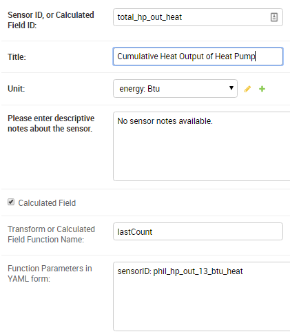
The only parameter necessary is the sensorID (Sensor ID) of the
rate-of-change sensor. This calculated function will then acquire and store the
last raw count that was used by the sensor to determine the rate of change.
Note that calculated functions only run every 1/2 hour, so the time resolution for these count values will be 1/2 hour, even if the counter reports at a more frequent interval.
Acquiring Building Energy Usage Information from ARIS
BMON can import building energy usage information from AHFC’s Alaska Retrofit Information System (ARIS). Configuring a sensor for the imported data is very similar to the process for acquiring weather data from the internet described above.
Using the administration interface, create a new Sensor ID. Title
and Unit entries are filled out as they are for standard sensors.
The Calculated Field box must be checked. The
Transform or Calculated Field Function Name must contain the value
getUsageFromARIS (correct capitalization is critical and must be as
shown). Finally, the Function Parameters in YAML form box must have
an entry of building_id: (there must be a space after the colon)
with a valid building id number from the ARIS database, and an entry of
energy_type_id: with a valid energy type value as described below.
Required Function Parameters in YAML form:
building_id: 1
energy_type_id: 1
Additional Optional Function Parameters in YAML form:
energy_parameter: 'EnergyQuantity'
energy_multiplier: 1
expected_period_months: 1
building_id Parameter
The easiest way to find a building_id value is to look on the ‘Commercial REAL Form’ in the ARIS user interface. When you select a building the building_id should show up in the upper left corner of the form.
energy_type_id Parameter
Possible values for the energy_type_id parameter:
1 Electric
2 Natural Gas
3 Propane
6 Coal
7 Demand - Electric
8 Demand - Nat Gas
10 Steam District Ht
11 Hot Wtr District Ht
12 Spruce Wood
13 Birch Wood
14 #1 Fuel Oil
15 #2 Fuel Oil
energy_parameter Optional Parameter
The energy_parameter specifies which value will be read from the ARIS database:
EnergyQuantity: The amount of energy used
DollarCost: The cost of energy for the given month
DemandUse: The amount of energy demand
DemandCost: The cost of energy demand for the given month, in dollars
A value of ‘EnergyQuantity’ will be used by default if you don’t include this parameter.
energy_multiplier Optional Parameter
The energy_multiplier is a multiplier that is used to scale the value that is read from the ARIS database. If you don’t include the parameter, a value of 1.0 will be used by default. The value that is stored is calculated as:
For EnergyQuantity:
[stored value] = [value from ARIS] * energy_multiplier / [total hours in the read period]For Costs:
[stored value] = [value from ARIS] * energy_multiplier / [standard length months in the read period]For DemandUse:
[stored value] = [value from ARIS] * energy_multiplier
expected_period_months Optional Parameter
In rare cases where the normal read period for the energy usage is something other than one month, you can enter a different number of months using this parameter. This value is used for estimating the previous read date when the date wasn’t set for the previous entry in ARIS, and for detecting missing data when the previous read date is more than 1.75 * [expected period months] earlier than the current read date.
Additional Required Settings
To use the BMON ARIS functionality you need to enter the URL, Username and Password in your installation’s settings.py file. The required settings parameters are:
BMSAPP_ARIS_URLBMSAPP_ARIS_USERNAMEBMSAPP_ARIS_PASSWORD
Estimating Pellet Consumption and Heat Output of an Okofen Pellet Boiler
A Periodic
Script
is available to collect data from Okofen Wood Pellet Boilers. One of the
Sensors indicates the Status of the boiler (the P241 sensor).
If the Boiler Status is in state 5 or 6, then the boiler is firing,
consuming pellets, and producing heat. A special calculated field has
been created, OkoValueFromStatus, that allows you to create a new
field showing the pellet consumption rate or the heat output rate of the
boiler for every 5 minute interval. Here is an example of the function
in use:
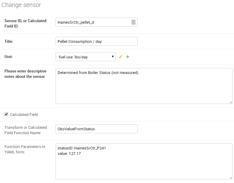
There are the two critical parameters that should be provided for the function, shown here with example values:
statusID: HainesSrCtr_P241
value: 127.17
The statusID parameter gives the Sensor ID of the boiler’s Status
sensor. For the example, the Sensor ID is HainesSrCtr_P241. When
this sensor reads a value of 5 or 6, the Okofen boiler is firing.
The value parameter is the pellet consumption rate or heat output
rate that occurs when the boiler is firing. For this example, that rate
is 127.17 pounds per day of pellets (the units were specified in the
Unit entry of the sensor).
The calculated field will generate pellet consumption rates or heat
output rates for each 5 minute interval spanning the available Status
data set. It is often useful to the use the Data Averaging feature
of the Plot Sensor Values over Time graph to see the average rates
across day, week, or monthly periods.
Deprecated Calculated Field Functions
Warning
Deprecated functions are described below and are present for backward
compatibility. Instead, use the genericCalc feature, described earlier in this
document, for new work.
Prior to development of the genericCalc function described above,
calculated fields were only possible for a few different types of mathematical
expressions. These specific types of calculated fields are described in this
section, however, the genericCalc approach should be used in their place;
the functions below are left available for backward compatibility reasons.
The table below shows these functions and use of the functions is explained in
the section following the table.
Function Name |
Expression Performed |
|---|---|
linear |
slope * val + offsetslope default is 1.0offset default is 0.0 |
AminusB |
A - B |
AplusBplusCplusD |
A + B + C + DC default is 0.0D default is 0.0 |
fluidHeatFlow |
flow * (Thot - Tcold * multiplier * (1.0-heat_recovery)heat_recovery default is 0.0 |
Each one of these functions can create a Calculated Field based by
applying a mathematical expression to a number of variables. The
mathematical expression that is used is shown in the
Expression Performed column of the table above. Each expression has
a number of variables. Each variable can either be a number or Sensor ID
(at least one of the variables must be a Sensor ID). Variables may
have default values, as indicated in the table above. If a variable has
a default value, it does not need to appear in the
Function Parameters configuration box. Here is an example for the
linear function:
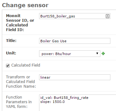
In this example, there already is a sensor that reports the firing rate
of a boiler as a percentage value varying from 0 to 100. We now want to
create a Calculated Field that displays the rate of natural gas use of
the boiler, expressed in Btu/hour. Because the gas use and the firing
rate of the boiler are linearly related, we can use the linear
Calculated Field function to create this gas usage field. Multiplying
the firing rate by 1500 will give the gas usage in Btu/hour since the
maximum gas usage of the boiler is 150,000 Btu/hour; a 100 firing rate
times 1500 gives a gas usage of 150,000.
The linear function has three variables: val, slope, and
offset. For our example, our conversion multiplier of 1500 is the
slope variable, and you can see its entry in the
Function Parameters in the above screenshot. The offset variable
is not needed in this application; BMON has a default value of 0.0 for
this variable, which is correct for our application, so therefore we
need not provide the variable in the Function Parameters box.
Finally, the val variable will be used for the Firing Rate sensor
values that we are using to calculate gas usage. Since this variable
needs to be filled in with sensor values, we need to preface the
variable with ``id_`` to indicate that this variable is a set of sensor
values. Then, the value provided for the variable in the
Function Parameters box is a Sensor ID:
id_val: Burt158_firing_rate
The id_ prefix on the variable val indicates that the variable
will be taken from an existing sensor. Burt158_firing_rate is the
Sensor ID of the firing rate sensor.
So, every 30 minutes BMON will gather up all of the
Burth158_firing_rate sensor readings that have not already been used
previously in this calculation, and BMON will multiply the by 1500 to
create additional sensor readings for the Burt158_boiler_gas sensor.
Here is a more complicated example that creates a Calculated Field that estimates the natural gas usage of a sidewalk snowmelt system based on measuring supply and return temperatures and the runtime of a circulating pump:
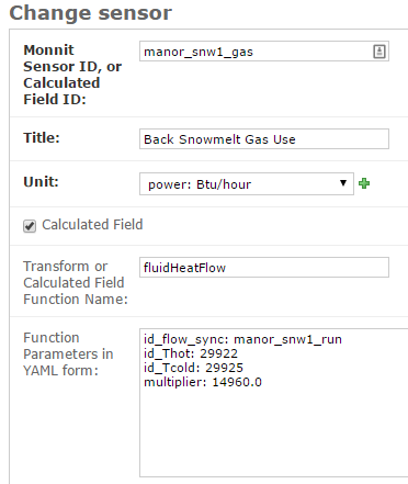
The Calculated Function being used here is the fluidHeatFlow
function, as described in the table above. You can see in the
Function Parameters box that the heat_recovery variable is not
provided in the configuration of this Calculated Field. Therefore, the
heat_recovery variable will assume its default value of 0.0. Three
of the variables in the math expression for the fluidHeatFlow
function come from existing sensor values: flow, Thot, and
Tcold. In the Function Parameter box, these variable names are
prefaced by the id_ prefix, indicating the values provided are
Sensor IDs. The multiplier variable is not a sensor value but
instead the constant 14960.0.
Finally, you can see that the flow variable appears in the
Function Parameter box as id_flow_sync. As explained before, the
id_ prefix indicates that the variable comes from a Sensor. The
_sync suffix indicates that the final calculated values for the new
sensor (manor_snw1_gas) should be synchronized on the timestamps of
this sensor. The other input sensor values (Thot and Tcold) will
be interpolated to these timestamp values when the calculation occurs.
If you have multiple sensor values entering into a Calculated Field, you
can add the suffix _sync to the variable whose timestamp values
should be used for the resulting calculated values. If you do not append
_sync to one of the variable names, one of the inputs sensors will
be used for synchronization, but it will not be easy to determine which
one.